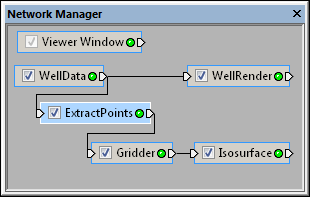
Select the ExtractPoints module in the Network Manager
to display its properties in the Property Manager.
Use the ExtractPoints module to extract
X, Y, Z, C data from well or lattice input.
The Network | Computational | Extract Points command adds an ExtractPoints module.
The ExtractPoints module converts points on well paths into points to use for gridding. It will also convert a lattice to a point data set. Users can specify the number of output components, based on the number of input log columns or components in the original lattice.
Well data or lattice data is the input type for the ExtractPoints module.
The ExtractPoints module creates point data. It may be connected to the Graphics Output Modules or the Computational Modules. An Info Module may also be connected to the output node.
For well data, the output X, Y, Z coordinates and components will be a double. For lattices, the X, Y, Z coordinates will be output as a double, but the components will be output with the same precision as the input components.
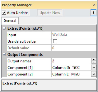
The properties of the ExtractPoints module are described below.
Select the ExtractPoints module
in the Network Manager
to display its properties in the Property
Manager.
Use the ExtractPoints module to
extract
X, Y, Z, C data from well or lattice input.
The Input property shows the source to which the module is connected. This option cannot be changed in the Property Manager, but can be changed in the Network Manager by changing the module input.
The Use default value option substitutes blank values in the well data or lattice with the Default value. Check the box next to replace blank values with the specified numeric value. Or, uncheck the box to leave blank values as blank in the output data.
After checking the box next to the Use default value, the Default value specifies the numeric value to use in the output. To change the value, highlight the existing value and type a new number.
Click the  next to Output Components to
open the Output Components section.
The Output names sets the number
of components being exported. This can be the same as the number
of input logs or input components from the lattice or a different number.
To change the number of output components, highlight the Output
names value and type a new value or click the
next to Output Components to
open the Output Components section.
The Output names sets the number
of components being exported. This can be the same as the number
of input logs or input components from the lattice or a different number.
To change the number of output components, highlight the Output
names value and type a new value or click the  button to increase or decrease the number of components. The Output
names is a value between 1 and 20. The maximum Output
names value is automatically limited by the number of components
from the input WellData or Lattice module.
button to increase or decrease the number of components. The Output
names is a value between 1 and 20. The maximum Output
names value is automatically limited by the number of components
from the input WellData or Lattice module.
The Component[1] option contains the name of the first component. For well data, the log name is listed. For lattices, the lattice component number is shown. To change the Component[1] name, click on the existing option and select the desired value from the list. Each additional component is listed as Component[2], Component[3], etc. The number of components listed matches the Output names value.
See Also