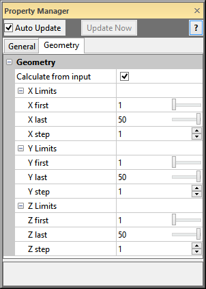
The Subset module Geometry page displays the extents and resolution of the output lattice. To open the Geometry page, click on the Subset module in the Network Manager. In the Property Manager, click on the Geometry tab.
This is an example of the information displayed
in the Property Manager on the Geometry
tab for a Subset module.
Check the box next to Calculate from input to have Voxler automatically calculate the extents of the output lattice based on the combined extents of the input lattices.
The X Limits item displays
the limits in the X direction for the lattice. Enter the X
first and X
last values. The X
first value is the first grid node to be extracted. The X
last value is the last grid node to be extracted. Values for X first and X
last are index values for the X direction. The first node in the
direction in the input grid is 1. The next node is 2, and so on. To
change the value, highlight the existing value and type the desired value
or click and drag the  to increase or decrease the
index grid node value.
to increase or decrease the
index grid node value.
The X step value indicates
how many grid nodes from the original lattice to skip. If X
step is set to 1, every grid node in the range from X
first to X last is used
in the output lattice. If X step
is set to 2, every other grid node is extracted. If X
step is set to 3, every third grid node is extracted, and so on.
To change the X step value, highlight
the existing value and type a new value or click the  button to increase or decrease the step value.
The Y Limits item displays
the limits in the Y direction for the lattice. Enter the Y
first and Y
last values. The Y
first value is the first grid node to be extracted. The Y
last value is the last grid node to be extracted. Values for Y first and Y
last are index values for the Y direction. The first node in the
direction in the input grid is 1. The next node is 2, and so on. To
change the value, highlight the existing value and type the desired value
or click and drag the to increase or decrease the
index grid node value.
The Y step value indicates
how many grid nodes from the original lattice to skip. If Y
step is set to 1, every grid node in the range from Y
first to Y last is used
in the output lattice. If Y step
is set to 2, every other grid node is extracted. If Y
step is set to 3, every third grid node is extracted, and so on.
To change the Y step value, highlight
the existing value and type a new value or click the
button to increase or decrease the step value.
The Z Limits item displays
the limits in the Z direction for the lattice. Enter the Z
first and Z
last values. The Z
first value is the first grid node to be extracted. The Z
last value is the last grid node to be extracted. Values for Z first and Z
last are index values for the Z direction. The first node in the
direction in the input grid is 1. The next node is 2, and so on. To
change the value, highlight the existing value and type the desired value
or click and drag the to increase or decrease the
index grid node value.
The Z step value indicates
how many grid nodes from the original lattice to skip. If Z
step is set to 1, every grid node in the range from Z
first to Z last is used
in the output lattice. If Z step
is set to 2, every other grid node is extracted. If Z
step is set to 3, every third grid node is extracted, and so on.
To change the Z step value, highlight
the existing value and type a new value or click the
button to increase or decrease the step value.
See Also