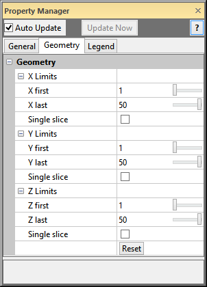
The FaceRender module Geometry page displays the extents of the FaceRender. To open the Geometry page, click on the FaceRender module in the Network Window. In the Property Manager, click on the Geometry tab.
This is an example of the information displayed
in the Property Manager on the Geometry
tab for a FaceRender module.
The X Limits item displays
the limits in the X direction for the FaceRender.
Enter the X first
and X last
values. The X first value is
the first grid node to be displayed. The X
last value is the last grid node to be displayed. Values for X first and X
last are index values for the X direction. The first node in the
direction in the input grid is 1. The next node is 2, and so on. To
change the value, highlight the existing value and type the desired value
or click and drag the  to increase or decrease the
index grid node value.
to increase or decrease the
index grid node value.
Check the Single slice check
box to view a single voxel
thick slice of the FaceRender
in the X direction. When the Single
slice check box is checked, the X
first value determines which grid node is visible. The X
last property is disabled since the slice is only one voxel
thick. The X first property is
stays limited to less than the X last
property when the Single slice
box is checked. Type the desired value into the X
first field to view a specific slice. Click and drag the
to pan through the volume.
The Y Limits item displays
the limits in the Y direction for the FaceRender.
Enter the Y first
and Y last
values. The Y first value is
the first grid node to be displayed. The Y
last value is the last grid node to be displayed. Values for Y first and Y
last are index values for the Y direction. The first node in the
direction in the input grid is 1. The next node is 2, and so on. To
change the value, highlight the existing value and type the desired value
or click and drag the to increase or decrease the
index grid node value.
Check the Single slice check
box to view a single voxel
thick slice of the FaceRender
in the Y direction. When the Single
slice check box is checked, the Y
first value determines which grid node is visible. The Y
last property is disabled since the slice is only one voxel
thick. The Y first property is
stays limited to less than the Y last
property when the Single slice
box is checked. Type the desired value into the Y
first field to view a specific slice. Click and drag the
to pan through the volume.
The Z Limits item displays
the limits in the Z direction for the FaceRender.
Enter the Z first
and Z last
values. The Z first value is
the first grid node to be displayed. The Z
last value is the last grid node to be displayed. Values for Z first and Z
last are index values for the Z direction. The first node in the
direction in the input grid is 1. The next node is 2, and so on. To
change the value, highlight the existing value and type the desired value
or click and drag the to increase or decrease the
index grid node value.
Check the Single slice check
box to view a single voxel
thick slice of the FaceRender
in the Z direction. When the Single
slice check box is checked, the Z
first value determines which grid node is visible. The Z
last property is disabled since the slice is only one voxel thick.
The Z
first property is stays limited to less than the Z
last property when the Single
slice box is checked. Type the desired value into the Z
first field to view a specific slice. Click and drag the
to pan through the volume.
Click the Reset button to return all of the values to the smallest and largest possible values. Clicking the Reset button does not uncheck any Single slice checkboxes.
See Also