Use the Annotation module to add
text to the screen that does not move
with the graphical output, such as the
The Network | Graphics Output | Annotation command adds an Annotation module.
The Annotation module creates a text string that is always parallel to the scene. The text appears attached to the screen and is not part of the scene; as such, the output from this module cannot be clipped by a clipping plane. By default, the current date and time is used as the text string. You can enter your own text in the Property Manager. Use the Text module to anchor the text to the scene. This can be useful to add text to the screen that does not move with the graphical output.
The Annotation module does not specify a bounding box for the text because the text is projected onto the screen and is not in the same coordinate system as the rest of the graph. If an Info module is attached, nothing is displayed for the bounding box.
The Annotation module is not connected to any module on the input side.
The Annotation module creates an output geometry. It may be connected to the Graphics Output Modules. An Info Module may also be connected to the output node.
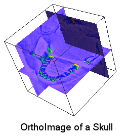
Use the Annotation module to add
text to the screen that does not move
with the graphical output, such as the
text "OrthoImage of a Skull" in this example.
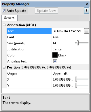
The Annotation module properties are described below.
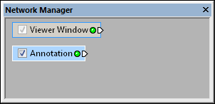
Select the Annotation
module in the Network Manager
to display its properties in the Property
Manager.
Change the Annotation settings in the Property Manager
to move the text or change the text that appears.
The Annotation module displays
an arbitrary screen-aligned text string. The text is always perpendicular
to the viewer's line of sight. By default, the current date and time are
used as the text string. Click the  button
to open the Multiline Text dialog
to enter custom annotation text. To create multiple lines of text, press
ENTER to start a new line. Click OK
to make the text change and view it in the Viewer
window. Click Cancel to return
to the properties without making the change.
button
to open the Multiline Text dialog
to enter custom annotation text. To create multiple lines of text, press
ENTER to start a new line. Click OK
to make the text change and view it in the Viewer
window. Click Cancel to return
to the properties without making the change.

Enter custom text in the Multiline
Text dialog.
The Font section specifies the text font. To change the font, click the current font and choose a new font from the list.
The Size (points) section determines
the size of the text in points. To change the value, highlight the existing
value and type a new value or drag the  to the increase or decrease the value.
The Justification indicates how multiple lines of text should appear. The Justification has no affect on a single line of text. The options available are Left, Center, and Right. To change the multiple line text Justification, click the existing option and select the desired option from the list. Choose Left to align the text to the left side of the text block. Choose Right to align the text to the right side of the text block. Choose Center to center all text in the text block.
The Color section specifies the text color. All text in the annotation has the same color. To change the color, click the colored box and choose a new color from the color palette. If the basic colors in the palette do not meet your needs, click Other to create a custom color.
Check the box next to the Antialias text option to make the fonts appear smoother by slightly adjusting the colors. This usually makes the text appear somewhat more dim.
Click the  next to Position to open
the Position section.
This section locates the text on the screen.
next to Position to open
the Position section.
This section locates the text on the screen.
The Origin is the Viewer window location where the annotation should be located. Available options are Upper left, Upper right, Lower left, and Lower right. To change the location, click on the existing option and select the desired location from the list. To further customize the location of the text, adjust the X and Y values. The Origin is relative to the X and Y values.
The X and Y
sections display the coordinates of the text in Viewer
window coordinates
ranging from 0.0 to 1.0. 0.0 places the Origin
of the text at the left edge for X
or the top edge for Y of the
Viewer window. 1.0 places the
Origin of the text at the right
edge for X or bottom edge for
Y of the Viewer
window. To change either value, highlight the existing value and type
a new value or drag the to increase or decrease
the value.
See Also