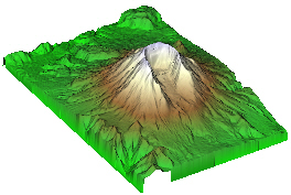
The example data for Mount St.Helens
without a ClipPlane module.
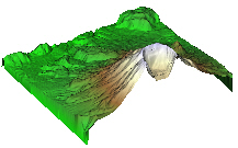
The example data for Mount St.Helens with a ClipPlane module. The ClipPlane module "clips" (does not draw) part of the geometry according to the user defined clipping plane.
The ClipPlane module clips input geometry according to a user-defined clipping plane. All geometry on one side of the plane is clipped (not drawn). The side that is clipped and the location of the clipping can be altered in the Property Manager. Multiple input modules may be connected to the same ClipPlane so that each module is clipped to the same values.
Multiple clip planes may be connected separately to the same module or connected in a series to a module. When connected separately to the same output geometry, effects like quarter cutouts, corner cutouts, etc can be accomplished. For example, one clip plane oriented along the X axis and a second clip plane oriented along the Y axis clips everything in three quarters of the plot.
geometry
The ClipPlane module creates an output geometry. It may be connected to the Graphics Output Modules. An Info Module may also be connected to the output node.
|
|
|
|
The example data for Mount St.Helens without a ClipPlane module. |
The example data for Mount St.Helens with a ClipPlane module. The ClipPlane module "clips" (does not draw) part of the geometry according to the user defined clipping plane. |
The ClipPlane module properties are described below.
Select the ClipPlane module in the Network Manager
to display its properties in the Property Manager.

Customize the ClipPlane properties.
The Input geometry property shows the source to which the module is connected. This option cannot be changed in the Property Manager, but can be changed in the Network Manager by changing the module input. If multiple modules are connected, each module is listed on a separate Input geometry line.
The Orientation is the direction of the clip plane normal. To change the orientation, click on the existing option and choose the desired option from the list. Options available are Along X, Along Y, Along Z, and Custom. The Along option clips the modules so that a portion of the data normal to the axis plane is removed. Custom allows the clipping to occur along a user defined plane.
The Normal Direction is the X, Y, and Z components of the normal to the clip plane. A plane is any flat, two-dimensional surface. A normal to a flat surface is a vector that is perpendicular to that surface. The ClipPlane is specified by the normal to the plane and an offset along the normal. The normal is specified by the X, Y, and Z components of a vector. The offset is the distance of the plane from the center of the input geometry. To change the X, Y, or Z component value, highlight the existing value and type a new value.
Distance from center is the distance of the clip plane from the center of the input geometry. A value of zero places the ClipPlane directly at the center of the input geometry. Larger positive values place the ClipPlane farther away from the center toward higher axis values. Smaller negative values place the ClipPlane farther away from the center toward the lower axis values. Units are in coordinate units. To change the distance, highlight the existing value and type a new value or click and drag the  to increase or decrease the distance location.
Check the box next to the Swap clip direction command to reverse the direction of the clip plane normal. This alters which portion of the area is displayed.
Check the Show dragger box to show the clip plane dragger and enable interactive rotation and offset. Invoke rotations by clicking and dragging the line parts of the three principal "axes" of the dragger geometry. Choose the solid middle part of the jack dragger axis to translate. See Dragger properties for more details.

Use the ClipPlane dragger (in gray
and white above) to interactively
change the position of the clip plane.
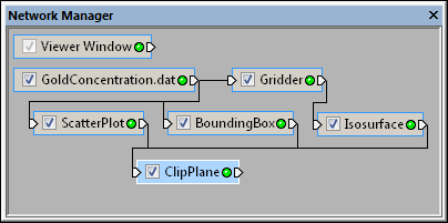
To connect multiple modules to a single ClipPlane, create each of the modules and add one ClipPlane to the network using the Module Manager or the Network | Graphics Output | ClipPlane command. Once the ClipPlane module appears in the Network Manager, you can connect your graphics modules to it. After dragging a connection from the graphics output to the ClipPlane, select which of the Connect Input Geometry Nodes to connect.
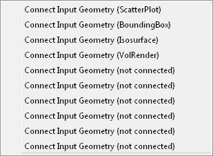
Select any of the available (not connected) Input Geometry
nodes when attaching a new module to the ClipPlane.
See Also