The WellRender module Path Data page contains the options to display continuous curve or log data along the well paths. All wells in the WellRender have the same properties applied. To open the Path Data page, click on the WellRender module in the Network Manager. In the Property Manager, click on the Path Data tab.
The WellRender module contains the following tabs in the Property Manager:
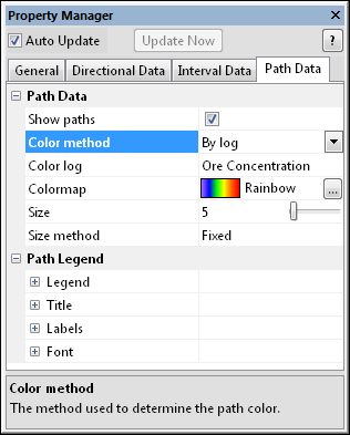
Path Data
Set the well path properties on the Path Data
tab in the Property Manager.
Check the box next to the Show paths option to display the well trace along the well path.
The Color method is the method used to generate the well log path. The color of the log may be set to a Fixed color or to By log, which matches a colormap with the log value. To change the Color method, click on the existing option and select the desired option from the list.
When set to Fixed, the Color option becomes available. The Color is the color of the well tube. To change the color, click on the existing color and select the desired color from the list. Alternatively, click the Other box to open the Colors dialog, where you can set custom colors.
When the Color method is set
to By log, the Colormap
option becomes available. To change the colormap used by the WellRender,
click the existing color bar to the right of the Colormap
command to select a different colormap from the list. Click on the desired
colormap and the WellRender updates.
Alternatively, click the  button to open the Colormap
Editor dialog. The Colormap Editor
dialog allows you to create a custom colormap and to change the mapping
of color to data values.
button to open the Colormap
Editor dialog. The Colormap Editor
dialog allows you to create a custom colormap and to change the mapping
of color to data values.
The Color log is the input log used to generate the color values. To change the log, click on the existing log name and select the desired log from the list.
The Size is the relative size
of the well trace tubes. The larger the value, the wider the well path
is. Values range from zero, which displays no path, to 200. To change
the path size, highlight the existing value and type a new value or click
and drag the  to increase or
decrease the well path.
to increase or
decrease the well path.
The Size method is the method used to determine the relative size of the path. Available options are Fixed and By log. When set to Fixed, the size is set by the Size option. When set to By log, the size is set with values from a log column. The Size log option becomes available, which contains the values that should be used to proportionally size the log. The largest size is determined by the Size value.
Show or hide the legend and change
its properties. Click the  to expand the
Path Legend section, where you
can change the properties of the path legend. This option is only available
when the Color method is
set to By log.
to expand the
Path Legend section, where you
can change the properties of the path legend. This option is only available
when the Color method is
set to By log.
See Also