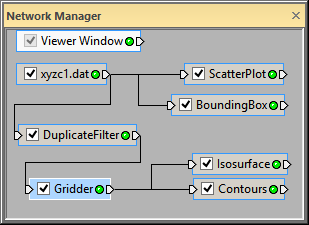
Click on the Gridder module and drag it to
To add another graphics output module to the Gridder module:
Click the Gridder module in the Network Manager.
In the Module Manager, double-click the Contours module in the Graphics Output section to connect it to the Gridder module. Alternatively, right-click on the Gridder module and select Graphics Output | Contours. The Network Manager now contains a connected Contours module and the Viewer window displays contours with the default settings.
To visualize the connections better, click on the Gridder module and drag it under the DuplicateFilter module.

Click on the Gridder module and
drag it to
a new location to visualize the connections better.
Sometimes, the default settings are not exactly what we want to show in the Viewer window.
To change the contour properties:
Click the Contours module in the Network Manager.
In the Property Manager, click on the General tab.
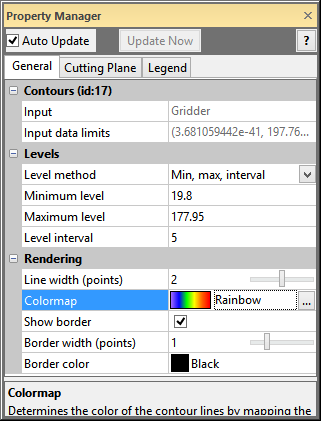
Click Automatic next to Level method and choose Min, max, interval. This property section allows you to set the minimum and maximum contour values, and the contour interval (number of units between contour lines).
In the Property Manager, double-click on the default Level interval value, type 5, and press ENTER.
In
the Property Manager,
locate the property named Colormap.
Click the sample color spectrum (GrayScale)
to the left of the  button to open the drop down
list. Click Rainbow
to change the colors of the contour lines.
With each contour property change, the contours update automatically in the Viewer window.

Adjust the Contours properties
in the Property
Manager.
Back to Connecting Multiple Modules
Next to Changing the Transparency