
Select the DuplicateFilter module in the Network Manager.

Adjust the module properties in the Property Manager.
You can add computational modules between the data file module and the Gridder module to change the isosurface. There are many data filtering options in Voxler. Filtering modifies the data stream, which affects all downstream modules. Typically, the "downstream" modules are automatically changed when "upstream" modules are altered. The Gridder module is one exception due to the time required to grid the data.
As an example of filtering our data, assume the data contains points that are very close together and we would like to combine these duplicate points into a single representative value.
To average these duplicate points:
1. Click the xyzc1.dat module in the Network Manager.
2. In the Module Manager Computational section, double-click the DuplicateFilter module to add it to the Network Manager. Alternatively, right-click on the xyzc1.dat module and select Computational | DuplicateFilter.
3. Click on the DuplicateFilter module in the Network Manager to select it.
4. In the Property Manager, change the Keep option to Median Z.
5. In the Property Manager, enter 20 for the Z Tolerance.
Select the DuplicateFilter module
in the Network
Manager.
Adjust the module properties in the Property
Manager.
Since there are no output modules currently connected to the DuplicateFilter module, there are no visible changes in the Viewer window. We can make changes by connecting the DuplicateFilter module to the Gridder module.
To connect the DuplicateFilter module:
1. First, move the DuplicateFilter module to the left side of the Network Manager so the connections are easily seen. Click on the DuplicateFilter module icon and drag it to the left side of the Network Manager.
2.
Click on the output connection
pad  on the right side
of the DuplicateFilter module
in the Network Manager.
on the right side
of the DuplicateFilter module
in the Network Manager.
3. In
the Network Manager, click the
input connection pad
on the left side of the Gridder
module to connect the two modules. The connection line changes from blue
to yellow when the cursor is over a module to which it can be connected.
The connection line color changes to black when the connection is completed.

Click on the DuplicateFilter output
connection pad and move
the cursor to the Gridder module
to connect the modules.
Since
the Gridder module accepts only
one input, connecting the DuplicateFilter module
causes the Gridder module to
automatically disconnect from the xyzc1.dat module.
In addition, the Gridder module
indicator LED turns yellow  indicating that
additional attention is required. Once the gridding
is complete, the Isosurface module
automatically updates and the new graphical output is sent to the
Viewer window.
indicating that
additional attention is required. Once the gridding
is complete, the Isosurface module
automatically updates and the new graphical output is sent to the
Viewer window.
To update the Gridder and Isosurface modules:
In the Network Manager, click the Gridder module to view its properties in the Property Manager.
In the Property Manager, click on the General tab.
Click the Recalculate button next to Data dependent parameters. This recalculates the lattice limits and other parameters to use the new input coming in from the DuplicateFilter module.
Click
the Begin Gridding button
in the Property Manager. The
progress gauge displays the gridding progress and the Gridder
module indicator LED turns green  when the gridding is complete. The Isosurface
module automatically updates with the new information and the results
display in the Viewer window.
when the gridding is complete. The Isosurface
module automatically updates with the new information and the results
display in the Viewer window.

Select the Gridder module in the Network
Manager to select it.

Adjust the Gridder properties and re-grid the data
to account for the new DuplicateFilter module.
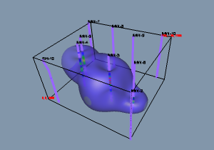
After the data are regridded, the Isosurface
automatically updates to reflect the changes
since it is "downstream" from the Gridder
module.
Back to A Note About Transparency