 on one module to another. The line is initially blue, but turns yellow when the cursor touches a compatible module. Release the mouse button to complete the connection. The line turns black when the connection is complete.
Module connections display the flow of data from one module to another.
Connect a module to other compatible modules by dragging a connection line from a connection pad  on one module to another. The line is initially blue, but turns yellow when the cursor touches a compatible module. Release the mouse button to complete the connection. The line turns black when the connection is complete.

An unconnected line appears blue.
In this example, the line between the Gridder and Isosurface modules
is not yet connected, but has been dragged from the Gridder node.

A connected (but unreleased) line appears yellow.
In this example, the line between the Gridder and Isosurface modules
is connecting the two modules, but the mouse button has not been released.

A connected (and released) line appears black.
In this example, the line between the GoldConcentration.dat, the Gridder,
and the Isosurface modules are all connected.
Alternatively, you can click on a connection pad, release the mouse button, and move the mouse without dragging. A blue connection line is drawn. The connection line turns yellow when the cursor is over a compatible module. Click the mouse button a second time to connect the two modules.
Another method to connect modules is to select one module in the Network Manager. Choose the Network | Connect command to connect either an input or output module to the selected module. Move the mouse until the connection line turns yellow. Click on the module and the two modules are connected.
To disconnect a module from the network, follow the directions above to make the same connection a second time. The disconnected module remains in the Network Manager and retains all other connections.
Modules can be rearranged in the Network Manager. You may need to move modules to see some connections clearly. Click on a module and drag it to a new location to move it or use the ARROW keys for fine adjustment.
Move an existing connection by left-clicking on a connection line, holding down the left mouse button, and dragging the line to a new connection pad.
Press the ESC key or click in an empty portion of the Network Manager to cancel a connection in progress.
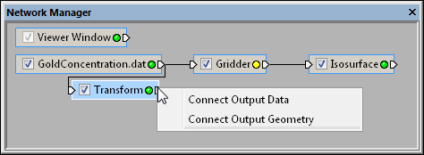
Some modules accept more than one input connection or provide more than one output connection. In these cases, a context menu is displayed when you click on the connection pad. Select the connection you want and proceed as previously described.

The Transform module provides output connections for data and geometry.
Select Connect Output Data to connect to the Isosurface module.
Modules can be connected and edited to see the effect of different parameters on the data. For example, a point set can be loaded, connected to a Gridder module, and displayed as an Isosurface module. You can experiment with the gridding parameters and immediately see the new output in the isosurface. The Isosurface module automatically recognizes that the lattice has changed and updates itself.
Multiple modules can be connected to a single module output connection to stack effects in the Viewer window. For example, Contours, Isosurface, and OrthoImage modules could all be connected to a single lattice module. The output from all three modules is correctly combined in the scene.
Change to the module location, visibility, and connection status can be undone using the Edit | Undo command.
The style of the connection lines can be customized using the Tools | Options command.
When attaching a module that is not compatible, the Voxler Error dialog appears.

The Voxler Error dialog appears when a non compatible module is attached to another module.
Click the OK button to remove the newly added incompatible module from the network.
See Also