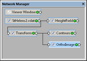
The Network Manager displays the visualization
network, which includes all loaded modules
and their connections.
Voxler uses a Network Manager to show a graphical representation (also referred to as a visualization network) of data and processes performed in the project. All data, modules, and processing paths for the current project are visible in the Network Manager. Modules are connected to perform a desired task. A module is a data set or process to be applied to a data set. Modules accept data on their input connection pads, modify the data, and pass it along through the output connection pads. The final output from the pipeline is usually a graphical representation of data, such as a HeightField or OrthoImage.

The Network Manager displays the visualization
network, which includes all loaded modules
and their connections.
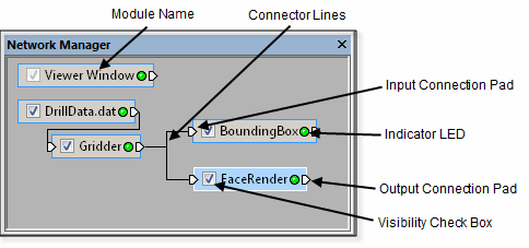
A small rectangle, that can be selected and dragged with the mouse, represents each module in the Network Manager. The module rectangles have the following components:

The sections of the Network Manager are marked in the
above diagram and described in the table below.
|
|
Visibility Check Box |
The visibility check box indicates whether a module's output is visible in the Viewer window. Check the box to display a module and all "downstream" (connected) modules. Uncheck the box to hide a module and all downstream modules. A gray check mark indicates that a module is disabled because of a hidden upstream module. |
|
(Name) |
Module Name |
Each module is named with the loaded data file name or by the function performed by the module. You can change the name with the Edit | Rename command. Alternatively, right-click the module and select Rename or press F2 on the keyboard. |
|
|
Indicator LED |
The indicator LED is a small round "light" showing module status. · Green · Yellow · Red |
|
|
Connection Pads |
An input connection pad is located on the left side of the module. An output connection pad is located on the right side of the module. The presence of connection pads indicates that a module may be connected to other modules. Only modules with the appropriate type of data may be connected. |
|
|
Connector Lines |
Connector lines are drawn between connected modules. Lines or pipes may be displayed. See the Tools | Options dialog to change the display of connector lines. |
To move a module, save a module, or change any of the module properties, select it by clicking the module rectangle in the Network Manager. The selected module is highlighted and its properties are displayed in the Property Manager. Note that only a single module may be selected at a time. Click in the Network Manager outside all modules to deselect all modules.
Right-click a module to display a context menu containing various commands that can be applied to the module. The commands include:
A list of modules that may be connected to the selected module. This is the fastest and easiest way to build a network. Simply right-click an existing module and select a module to connect.
A Connect command, which allows you to connect existing modules interactively. The command name changes depending on the selected module type. See Connecting Modules for more information about this procedure.
A Save Data command, which allows you to save the module's data output.
A Copy command, which copies all properties of the selected module. This is useful for creating an exact duplicate of an existing module.
A Rename command, which allows you to rename the selected module to any other name.
A Delete command, which removes the selected module from the Network Manager. Deleting a module removes the links to other modules.
Right-click in the Network Manager without a module selected to display a different context menu that includes commands to import a new file, create standalone modules, or paste a copied module. Standalone modules, such as Annotation, do not require an input connection. When right-clicking to add modules, the module appears in the location where you right-clicked.
When an icon is dragged outside the limits of the Network Manager, scroll bars are added to allow scrolling to the portions of the network that are not visible.
The following keyboard commands are available in the Network Manager:
The DELETE key deletes the selected module if the Network Manager is active.
The TAB key cycles through the modules in the order they were added.
SHIFT+TAB cycles through the modules in the reverse order.
The ARROW keys move the selected module.
The Viewer window module is automatically created by Voxler and cannot be deleted or made invisible in the Network Manager. This module is used to control various settings that affect the entire scene, such as background color.
See Also