 button,
so all modules are visible. Expand
the Graphics Output folder. Double-click
on the Contours module in the
Module Manager to load the module
in the Network Manager.
button,
so all modules are visible. Expand
the Graphics Output folder. Double-click
on the Contours module in the
Module Manager to load the module
in the Network Manager.There are several ways to connect or disconnect two modules. After you have selected a module:
Right-click on a module in the Network Manager and select Connect from the context menu
Click on the connection pad of a module in the Network Manager
Click the Network | Connect command
The procedure is the same whether you are connecting or disconnecting two modules. Once a Connect command is initiated, the cursor snaps to the Network Manager and Voxler enters graphical connect mode. Move the mouse until the blue connection line touches the compatible module you want to connect to or disconnect from and the connection line turns yellow. Click the mouse on the module to make or break the connection. The blue connection line turns yellow if the modules are compatible.
The Connect command menu text differs depending on which module is selected.
Start with a new window. If a Voxler file is already open, click the File | New command to open a new blank window.
In the Module Manager,
click the  button,
so all modules are visible. Expand
the Graphics Output folder. Double-click
on the Contours module in the
Module Manager to load the module
in the Network Manager.
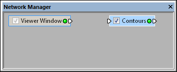
A module can be added to the Network Manager
without being connected to any data.
In the Module Manager, expand the Data Source folder. Double-click on the TestLattice module to load a test lattice. The test lattice is automatically selected in the Network Manager.
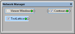
Additional modules can be added to the
Network Manager without being connected.
Right-click on the TestLattice module and choose Connect Output Lattice.
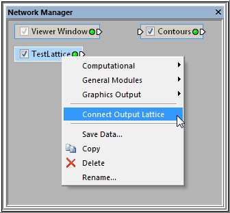
Choose the Network | Connect Output Lattice
command to connect the Contours
module
to the TestLattice module.
The blue connection line appears in the Network Manager.
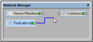
When the Network
| Connect Output Lattice command
is
selected, a blue connection line appears.
Move the cursor to the Contours module and the blue line changes to yellow.
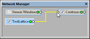
The connection line changes to yellow when it is over a
module that can be connected to the selected module.
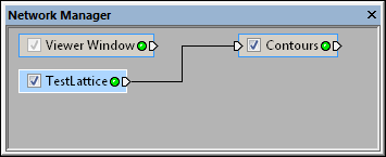
When the connection line changes to yellow, left-click to make the connection. The connection line becomes a black line and the contour map displaying the TestLattice data appears in the Viewer window.
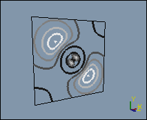
The contour map is displayed in the Viewer
window when the Contours
module is connected to the TestLattice
module.
To disconnect the two modules, right-click on the Contours module and choose the Connect Input Lattice (TestLattice) item.
A blue line appears between the Contours module and the cursor. Move the cursor over the TestLattice module and the connection line turns yellow. Left-click on the TestLattice module in the Network Manager to break the connection.
See Also