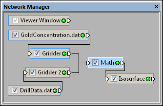
Select the Math module in the Network Manager
to display its properties in the Property Manager.
The Network | Computational | Math command adds a Math module.
The Math module creates a new output lattice from one or more input lattices by applying a numeric expression to one or more input lattices. The output lattice is calculated one node at a time by applying the numeric expression to the input lattice nodes.
It is NOT necessary for the input lattices to be have identical X, Y, or Z ranges. This module is currently limited to a maximum of 3 input lattices.
When evaluating expressions that may contain 'no data' (either NULL, or blank) values as part of a grid file, the Math module can specify which numeric value is to be treated as 'no data'. See the Math Module Examples page for sample math expressions.
Lattice is the input type for the Math module.
The Math module creates a uniform lattice. It may be connected to the Graphics Output Modules or the Computational Modules. An Info Module may also be connected to the output node.
The Math module properties are described below.
Select the Math module in the Network Manager
to display its properties in the Property Manager.
The Math module contains the following tabs in the Property Manager:
General

Enter a numeric expression to define
the generated lattice values.
Next to Input lattice A, Input lattice B, and Input lattice C, are the module names of the lattices attached to the math module. These can be changed by connecting a different lattice module to the Math module.
The Output type is the format that is used to save the output lattice. To change the type, click on the existing option and select the desired output lattice type from the list.
Click the  next to Output Components to open the section and display the output component options. The Output components is the number of components to create in the output lattice. To change the number of components, highlight the existing value and type the desired value or click the
  to increase or decrease the number of components.
The Expression[1] is the mathematical equation that will create the first component in the output lattice. The math module can have between one and 100 expressions which create that number of components in the output lattice. To change the equation, highlight the existing text and type the equation, in the form A + B + C. A, B, and C refer to the input lattice components. When used without a number after the letter, the first component is used. When used in the form A1+B2+C4, the letter refers to the input lattice and the number is the component where 1 is the first component of the input lattice, 2 is the second, and so on.
To use the X, Y, or Z values in the equation, type the letter X, Y, or Z in the expression. The X, Y, and Z value of the node being calculated is used in the equation for that node.
The index value of the current node can also be used in the equation. To use the index value, type the letter i, j, or k in the equation for the X, Y, or Z position. The i is the X node index, j is the Y node index and k is the Z node index. The first node in each direction has the value 1. The next node in each direction has the value 2 and so on.
If the function cannot be evaluated, the corresponding lattice node is blanked.
See Also