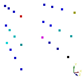
This is a scatter plot display of a 2x3x4 lattice
created from a .P3D and .Q file.
Use Plot-3D files .P3D and .Q to import a regularly spaced lattice that is in ASCII format. The .P3D and .Q files can be created in a text editor, like Notepad. Both files need to have the same name so they can read each other.
P3D File
The top line the P3D file shows how many nodes there are in the lattice (X, Y, Z). Then, all of the X values are listed, all of the Y values are listed, and all of the Z values are listed. The order for the points is X increasing while Y and Z stays the same. At the end of the max X, increase to the next Y value continue until all X values are listed for all Y values at the lowest Z. Then, increase to the next Z and repeat the listing of X values at each Y. After all X values are listed, list all Y values. This is the Y value associated with the X value at the same location. Then, all Z values are listed. This is contained in the P3D file.
Q File
The Q file contains the same initial row header and then four cells of zeros, the component information for each node (in the same order as the XYZ data), and then another set of zeros. To determine how many zeros to include at the end of the file, multiple the grid size by 4.
Example
This is an example of a 2x3x4 regular lattice (P3D and Q files).
Choose the File | Import command.
Select the .P3D file. Accept default values in Import dialog.
The your-file-name.p3d data module is added to Network Manager.
Right-click on the module and select Computational | ScatterPlot. A scatter plot of the 2x3x4 lattice is displayed.

This is a scatter plot display of a 2x3x4 lattice
created from a .P3D and .Q file.
See Also