
The Cutting Plane properties may be changed to
affect the orientation ("normal") of the cutting plane.
The Cutting Plane, a property of some modules, determines the orientation ("normal") of the cutting plane. You can choose one of the preset local axis plane normal, or you can choose an arbitrary direction by entering values for X, Y, and Z. The plane normal may be specified numerically with the Normal Direction property or graphically when the dragger is shown.
The Cutting Plane properties are described below. This feature may be accessed via the Contours, ObliqueImage, and Slice modules.
The Cutting Plane properties may be changed to
affect the orientation ("normal") of the cutting plane.
To change the Orientation, click on the existing option and select the desired option. Choose one of the preset local axis plane normals— XY plane (axial), XZ plane (coronal), or YZ plane (sagittal)— or choose Custom to enter custom Normal Direction values. Axial indicates the XY plane that travels horizontally. Coronal indicates the XZ plane that travels vertically. Sagittal indicates the YZ plane that travels vertically. The Custom setting lets you type a value under Normal Direction for each axis.
 |
 |
 |
 |
|
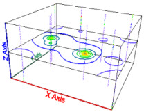
The contours Orientation is set to XY plane (axial). |
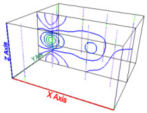
The contours Orientation is set to XZ plane (coronal). |
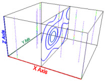
The contours Orientation is set to YZ plane (sagittal). |
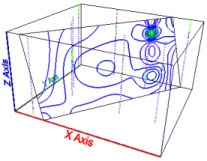
The contours Orientation is set to Custom. |
Enter a value under Normal Direction for the X, Y, and Z components of the plane normal. Changing these values changes the cutting plane orientation with respect to the normal for that axis. Changing the X value when the Y and Z values are zero creates a YZ cutting plane. Setting each of the X, Y, and Z values to 1 produces a plane with an oblique orientation. This vector is the normal to the cutting plane.
The Offset from center property measures the distance of the cutting plane from the center of the lattice. To change the offset, highlight the existing value and type a new value or click and drag the  to increase or decrease the distance from the center. Units are in axis units. If the X axis goes from 0 to 60, a value of 0 for the Offset from center will place the plane at X= 30. A value of just less than 30 will place the plane at the maximum X value. A value of just greater than -30 will place the plane at the minimum X value.
The Dragger allows interactive positioning and rotation of the plane.
Check the Show dragger box to show the dragger— a virtual, rotatable trackball— and allow interactive positioning and rotation of the plane. The dragger allows the orientation and offset of the cutting plane to be specified.
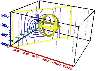
The Dragger is shown above in yellow and can be
used to interactively rotate the cutting plane.
Drag one of the three bands to rotate around a principal axis in the direction of the ring. Drag anywhere on the ball (between the rings) to perform an unconstrained rotation in any direction.
To specify a user-defined rotation axis, press the SHIFT key while clicking the left mouse button and dragging. A new distinctively-colored axis is added.
To scale the size of the trackball, press the CTRL key and drag the trackball.
To offset the plane in the perpendicular direction, drag the cutting plane itself.
See Also