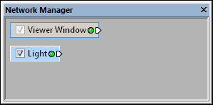
Select the Light module in the Network Manager
to display its properties in the Property Manager.

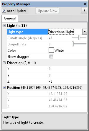
Change the light properties
in the Property Manager.
The Network | General Modules | Light command adds a Light module to the Viewer window.
The Light module creates a new directional, point, or spot light and adds it to the scene. Lights are cumulative. Every time a new light is added, the scene becomes a little brighter. You can add approximately seven lights to the scene.
The headlight is automatically attached to the camera, which can make it difficult to see the affect of added lights. To view a scene with only light modules, uncheck the View | Headlight command to turn off the global light.
Lights may be positioned and oriented numerically, or by enabling the dragger in the Property Manager.
The Light module is added to the scene, not an individual module. The Light module is not connected to any module on the input side.
The Info and ClipPlane modules can be connected to a Light module on the output side. Adding the Info module provides information about the light. Adding a ClipPlane module limits the light to only certain locations in the scene.
The Light module properties are described below. Click on the Light module in the Network Manager. The properties are displayed in the Property Manager.

Select the Light module in the Network Manager
to display its properties in the Property Manager.

Change the light properties
in the Property Manager.
To change the Light type, click on the existing light type option and select the desired option from the list. Available options are Directional light, Point light, or Spot light to brighten the image and create special effects.  Each type of light has different properties and displays differently in the Viewer window.
For a Directional light, the Direction X, Y, and Z properties specify a direction vector pointing in the direction the light rays travel. Directional lights do not have a position; only the direction is relevant.
 For a Point light, the Position X, Y, and Z specify the position of the light source in map coordinates. The light radiates outward from the source symmetrically in all directions like a star.
 A Spot light has both a Direction and a Position. Like a theatrical spotlight on a stage, the spot light illumination is a cone of light diverging from the light's Position. The axis of the cone is oriented according to the specified Direction. The location of the spot light is defined by the Position.
The Color option changes the color of the light source. This can affect the color of the modules being displayed in the Viewer window. To change the color, click on the existing color and select a new color from the color palette.
Check the box next to the Show dragger command to show the light dragger so it can be interactively adjusted in the Viewer window. The light dragger is scaled to be a reasonable size according to the existing geometry at the time the dragger is turned on. If new geometry is added or removed, the dragger size may become too large or small relative to the new geometry. In this case, it may be necessary to turn the dragger off and on in order for Voxler to display the dragger at a proportionate size to the new geometry.
The Directional light dragger can be moved or reoriented; however, the actual position of the dragger is irrelevant. Drag either end of the arrow to reorient the light.
The Point light dragger can only be moved. Drag the spherical portion to move the dragger in the plane. Drag the rectangular bar to move the dragger perpendicularly to the plane.
The Spot light dragger can be moved, oriented, and have its cone angle adjusted. Drag either end of the arrow to reorient the direction of the light. Move the spherical portion to adjust the position of the light. Drag the rectangular bar to move the dragger perpendicularly to the plane. Drag the cone to adjust the Cutoff angle (degrees). See Dragger properties for more details.

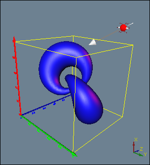
With the Show Dragger option on, the light
source can easily be moved and adjusted. This
example shows a blue Directional Light.
For Directional light and Spot light types of light, enter the X, Y, and Z vector values in the Direction section. The direction values can be manually adjusted in the Property Manager, or automatically adjusted using the Dragger. The Direction values are in vector units. A value of 0 will have no light in that direction. Values in the X, Y, and Z boxes are combined to get the vector direction. To change the value, highlight the existing value and type a new number.
For Point light and Spot light types of light, enter the X, Y, and Z light location in the Position section. The position values can be manually adjusted in the Property Manager, or automatically adjusted using the Dragger. The Position values are entered in map units. To change the value, highlight the existing value and type a new number.
For a Spot light, you can enter a value into the Cutoff angle (degrees) box. The cutoff angle box can be manually adjusted in the Property Manager, or automatically adjusted using the Dragger by altering the cone angle. The Cutoff angle (degrees) defines how light diverges from the spot light source. Values range between approximately 0 and 90. A value of zero would be equivalent to a directional light. A value of 90 would be equivalent to a spot light. To change the value, highlight the existing value and type a new value or drag the  to the desired level.
For a Spot light, you can enter a value into the Dropoff rate. The dropoff rate is the rate at which the light intensity drops off from the primary direction. The dropoff rate is a value between 0 and 1. To change the value, highlight the existing value and type a new value or drag the  to the desired level.
See Also