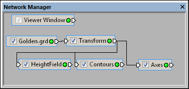
Select the Transform module in the Network Manager
to display its properties in the Property Manager.
The Network | Computational | Transform command adds a Transform module.
The Transform module transforms the X, Y, and Z coordinates of an input data set or lattice using a standard 4x4 transformation matrix. The order of transformations is Scale, Rotation, Translation. Rotation and scaling are performed around the object's Origin.
Lattice, point data, and well data are input types for the Transform module.
The Transform module creates lattice, point data, and well data depending on the input type. It may be connected to the Graphics Output Modules or the Computational Modules. An Info Module may also be connected to the output node.
Two types of output modules— data and geometry— may be connected to the Transform module. To see this in action, click the output connection pad of the Transform module. A context menu appears with two choices: Connect Output Data and Connect Output Geometry. Choose Connect Output Data to connect a module that contains transformed lattice or point data, e.g., Isosurface or ScatterPlot. Choose Connect Output Geometry to connect a module that contains output geometry, e.g., ClipPlane. The output geometry is the dragger graphics. If the dragger is turned off, there is no output geometry.
The Transform module properties are described below.

Select the Transform module in the Network Manager
to display its properties in the Property Manager.
The Transform module contains the following tabs in the Property Manager:
General

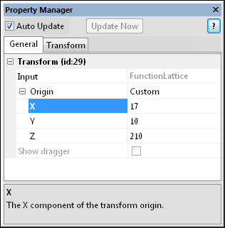
Change the Transform module properties
in the Property Manager.
The Input property shows the source to which the module is connected. This option cannot be changed in the Property Manager, but can be changed in the Network Manager by changing the module input.
The Origin is the location about which the Transform Scale and Rotation are performed. To open the Origin section, click the  next to Origin. Available options are Center, Lower left, Upper right, and Custom. To change the Origin, click on the existing value and select the desired option from the list.
When the Origin is set to Center, all scaling and rotations are performed about the X, Y, and Z midpoints of the original data. This was the method used by Voxler 1 and 2. When the Origin is set to Lower left, scaling and rotations are performed about the X, Y, and Z minimum values. When the Origin is set to Upper right, scaling and rotations are performed about the X, Y, and Z maximum values. When the Origin is set to Custom, scaling and rotations are performed about the specified X, Y, and Z values. The X, Y, and Z value options are only editable when the Origin is set to Custom. To change the X, Y, and Z values, highlight the existing value and type the desired value. Values are in map coordinates.
 Show Dragger
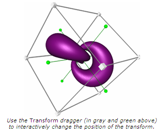
Check the box next to the Show dragger option to allow interactive adjustment of the transform. This option is only available when the Origin is set to Center. The dragger supports adjusting the scale, rotation, and translation.
To use the dragger to change the scale, check the box next to Show dragger. In the Viewer window, drag the corner cubes of the dragger to change the scale. Uniform scaling is performed on the Transform, changing the X, Y, and Z values by the same amount. To change the Scale values by different amounts, press and hold the SHIFT key before selecting a corner cube. The dragger can then be dragged in various directions to change the scaling values. Hold down the CTRL key before selecting a corner cube to scale uniformly toward a corner point.
Click and drag any of the six green circle end markers of the dragger axis cross to change the rotation manually. The initial drag direction determines the orientation in which the rotation is performed. Hold down the SHIFT key before selecting the marker to rotate in a free form fashion around the sphere.
Click and drag any of the gray sides of the dragger to change the translation manually. Hold down the SHIFT key before selecting any side to lock translation to a single axis in the plane. Hold down the CTRL key before selecting a side to translate along the plane's normal vector. Translation is performed in the plane of the selected side.
See Also