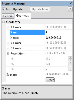
The lattice source module Geometry page displays the extents of the lattice. To open the Geometry page, click on the lattice source module in the Network Manager. In the Property Manager, click on the Geometry tab.

This is an example of the information displayed
in the Property Manager on the Geometry
tab for a lattice source module.
The X Limits item displays the limits in the X direction for the function lattice. Enter the X min and X max coordinates. These ranges are the limits of the lattice that is created. The values are in map coordinates. To change the values, highlight the existing value and type the desired minimum or maximum value.
The Y Limits item displays the limits in the Y direction for the function lattice. Enter the Y min and Y max coordinates. These ranges are the limits of the lattice that is created. The values are in map coordinates. To change the values, highlight the existing value and type the desired minimum or maximum value.
The Z Limits item displays the limits in the Z direction for the function lattice. Enter the Z min and Z max coordinates. These ranges are the limits of the lattice that is created. The values are in map coordinates. To change the values, highlight the existing value and type the desired minimum or maximum value.
Resolution is the number of nodes in the lattice. For a lattice source module, these values cannot be changed. The Resample module may be used to calculate a new lattice with a different size or resolution.
Spacing displays the distance between nodes in the X, Y, and Z directions. This property cannot be changed.
Click the Reset button to restore the coordinates in the X Limits, Y Limits, or Z Limits sections to their original values as loaded from the file.
See Also