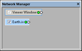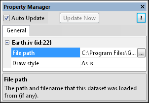
Select a geometry data set in the Network Manager
to display its properties in the Property Manager.

Select a geometry file in the Network Manager to
display its properties in the Property Manager.
Geometry source modules are created when an Inventor .IV, AutoCAD DXF, Esri SHP, Golden Software BLN file or other type of geometry file is loaded. It may be useful to draw geometry source modules in different styles, including Shaded, Lines, or Points.
Defined from the geometry defined in the file.
A ClipPlane Module, Info Module, and BoundingBox can be connected to the output node.
Click on the geometry source module in the Network Manager to select it. The properties are displayed in the Property Manager. The geometry source module properties are described below.

Select a geometry data set in the Network
Manager
to display its properties in the Property
Manager.

Select a geometry file in the Network
Manager to
display its properties in the Property
Manager.
The path of the loaded source file appears next to File
path. Click the  button to the right of the file
path to display the Open
dialog. The Open dialog appears.
The currently loaded file name is display in the File
name section. The path for the current file is shown. Click the
Open button to reload the current
file. This can be used to update the network after the data file has been
modified.
Alternatively browse and select a new file. Click the Open button to load the new file. The dialog closes and the selected file is loaded. If the new file does not display geometry information, a warning message will appear and the original file remains.
The Draw style option can be used to force the geometry to display in a certain way, overriding the drawing styles specified within the loaded file. The Draw Style options are As is, Shaded, Lines, or Points.
|
|
|
The Earth.IV file with a Draw Style of Shaded. |
The Earth.IV file with a Draw Style of Lines. |
The Earth.IV file with a Draw Style of Points. |
See Also