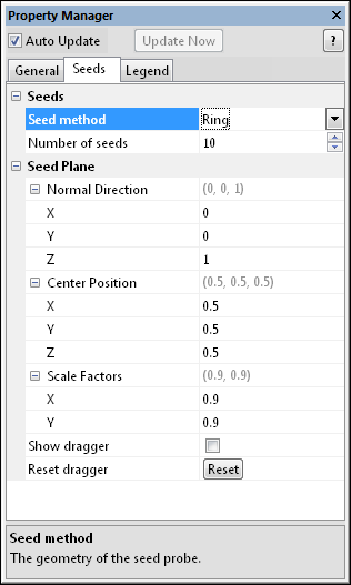
The StreamLines module Seeds page displays the starting location for all the points where streamlines should appear. To open the Seeds page, click on the StreamLines module in the Network Window. In the Property Manager, click on the Seeds tab.

This is an example of the information displayed
in the Property Manager on the Seeds
tab for a StreamLines module.
The Seed method specifies the geometry of the seed probe. Available options are Line, Ring, Square, and Point set. To change the method, click on the existing option and select the desired option from the list.
The Line method starts all seeds on a single line. The Ring method starts all seeds in a circle. The Square method to use the specified number of seed points as the number of seeds per side of the square. This results in the Number of seeds being squared.
The Point set option requires a data file connected to the StreamLines module. The data file contains the points where seeds should be started. This allows more control over seed point placement. In this case, the first N points are loaded from the connected point set, where N is the number of seed points specified in the Number of seeds option.
The Number of seeds contains the number of starting locations for streamlines. To change this value, highlight the existing value and type a new value or click and drag the  to increase or decrease the number of seeds. Values range from 1 to 100. The larger the value, the longer it will take to generate the streamlines and the more streamlines will appear.
Click the  to open the Seed Plane section. This section controls the initial placement of the seeds.
The Normal Direction is the direction of the normal (perpendicular vector) to the plane containing the seed points. Click the  to open the Normal Direction section. The normal direction has an X, Y, and Z component. To change the normal direction, highlight the existing value and type a new value.
The Center Position is the position of the plane containing the seed points (in world coordinates). Click the  to open the Center Position section. The center position has an X, Y, and Z component. To change the center position, highlight the existing value and type a new value.
The Scale Factors are the scale factors for the seed plane. A scale factor of 1.0 makes the seed distribution as wide as the X or Y extents of the volume. Click the  to open the Scale Factors section. The scale factors have an X and Y component. To change the scale factor, highlight the existing value and type a new value.
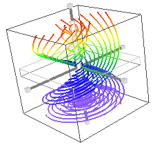
Check the box next to the Show dragger option to display a jack dragger that allows the seed points to be moved or rotated graphically. When the dragger is visible, the seed point locations are lighted green.

The StreamLine dragger is used to
interactively change the position of the seed plane.
Invoke rotations by clicking and dragging the line parts of the 3 principal "axes" of the dragger. Uniform scale operations can be completed by dragging any of the 6 cubes.
Translation is performed with the dragger by picking the flat transparent box or the solid middle part of the axis. Pressing the SHIFT key while translating the planar portion constrains to one of the principal axes.
Click the Reset dragger button to reposition the dragger and seed point locations back to the XY plane in the center of the lattice.
See Also