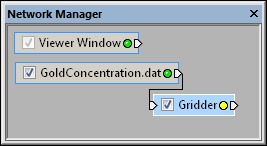
 . After specifying
the gridding properties and clicking the Begin
Gridding button, the indicator light changes to green
  to specify that the module is up to date and ready to add addition
modules.
to specify that the module is up to date and ready to add addition
modules.The Network | Computational | Gridder command adds a Gridder module.
The Gridder module interpolates scattered point data onto a uniform lattice. This type of lattice is used to create several types of output graphics, including Isosurfaces, VolRenders, FaceRenders, VectorPlots, and StreamLines. Other graphics can be created from slices through a uniform lattice, including Contours, HeightFields, OrthoImages, and ObliqueImages.
A uniform lattice is a one-, two-, or three-dimensional orthogonal array of data points arranged in the XYZ directions with points equally spaced in each direction. The distance between data points in the X, Y, and Z directions is the same throughout the lattice, but the X separation distance is not necessarily the same as the Y or Z separation distances.
The Gridder module is also used to calculate data values in areas where there are no data.
The range and resolution of the output lattice may be specified along
with the interpolation method and
associated parameters. Since gridding
can take quite a while to execute, it is necessary to click the Begin Gridding button to start
the process. No output is generated until this is done. The Gridder
module in the Network Manager
will display a yellow LED indicator light  . After specifying
the gridding properties and clicking the Begin
Gridding button, the indicator light changes to green
  to specify that the module is up to date and ready to add addition
modules.
Point data is the input type for the Gridder module.
The Gridder module creates a uniform lattice. It may be connected to the Graphics Output Modules or the Computational Modules. An Info Module may also be connected to the output node.
The Gridder module properties are described below.

Select the Gridder module in the
Network Manager
to display its properties in the Property
Manager.
The Gridder module contains the following tabs in the Property Manager:
General

View and change the gridding method in the Property
Manager. Click the Begin Gridding button to
begin the gridding process.
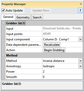
The Input property shows the source to which the module is connected. This option cannot be changed in the Property Manager, but can be changed in the Network Manager by changing the module input.
The Input points item displays the number of points in the point set.
The Input component property is shown if the input set has more than one component. The Input component property specifies which data component to grid if the input data set has more than one component. To change which component is used by the Gridder module, click the current selection in the Input component field and select the desired component from the list. The Input component list contains the components specified in the Data Source properties for the module displayed by the Input property.
The output lattice is always a single component, i.e., the Gridder module grids only one component at a time, even if the input data set has multiple components.
Click the Recalculate button to calculate default values based on the input data. This function is helpful when the input data has changed or the Gridder module is connected to a new data set and the old values are no longer appropriate.
Action
Click the Begin Gridding button to begin the gridding process. The Progress dialog appears and displays the gridding progress.
The Gridder module indicator LED in the Network Manager glows yellow when the Gridder module needs to be updated. Once the Begin Gridding button has been clicked and the module finishes gridding, the light changes to green.
Click the  next to Method to open the Method section where gridding options
are set.
The differences between gridding methods are in the mathematical algorithms used to compute the weights during lattice node interpolation. Each method can result in a different representation of the data. You may want to test each method with a known data set to determine the method that provides you with the most satisfying interpretation of the data.
The default method is Inverse distance. This method produces the best results in most cases. To change the method, click on the existing option and select the desired method from the list. Choose Data metric, Inverse distance, or Local polynomial as the interpolation method to use for generating the output lattice.
The Metric option is available when the Method is set to Data metric. The Metric controls the type of data metric being calculated by the gridding algorithm. To change the metric, click on the existing option and select the desired option from the list.
The Order option is available
when the Method is set to Local polynomial. The order is
the local polynomial order for the interpolation. The Order
is 0, 1, 2, or 3. The larger the order, the more complex the local polynomial
equation can be. To change the Order,
highlight the existing value and type the new value or click the  to increase or decrease the order.
The Power option is available when the Method is set to Inverse distance or Local polynomial. The power is the exponent in the inverse distance weighting formula or the local polynomial weighting formula. To change the power, highlight the existing value and type a new value.
The Smooth option is available when the Method is set to Inverse distance. The smooth value controls the amount of smoothing in the interpolation. The higher the value, the more smoothing occurs. To change the value, highlight the existing value and type the desired value.
The Anisotropy property of the Inverse distance gridding method lets you specify that data points in one direction from the lattice node have a higher weight than points in another direction. Points closer to the grid node are usually given more weight than points farther from the grid node, regardless of direction. If the points in one direction have more similarity than points in another direction, it is advantageous to give points in a specific direction more weight in determining the value of a lattice node. The relative weighting is defined by the anisotropy lengths of the three axes of the search ellipse or ellipsoid.
The available options for the Anisotropy setting are Isotropic, Anisotropic, and General. Isotropic sets all directions to equal weighting. Anisotropic allows an Ellipse to be specified to set the direction of weighting. The ellipse axes are parallel to the X, Y, and Z axis directions. General allows each axis of the 3D ellipse to be manually altered. The ellipse is specified with vectors defined by the ray going from 0, 0, 0 to the X, Y, Z values specified. To change the Anisotropy setting, click on the existing option and select the desired option from the list.
When the Anisotropy is set
to Anisotropic or General,
the Ellipse option is available.
To open the Ellipse section,
click the  next to Ellipse.
For an Anistropic ellipse, the options available are X length, Y length, and Z length. To change these values, highlight the existing value and type a new value. The lengths are relative and in data file units. For example, if you specify the X length equal to 2, the Y length equal to 4, and the Z length equal to 1, the Y direction is given the most weight and the Z direction is given the least weight. Points that are 4 units away in the Y direction have the same weight as points that are 1 unit away in the Z direction.
For a General ellipse, open
the First Axis, Second Axis,
or Third Axis sections by clicking
the  next to the section name.
Each section has an X, Y, and
Z value, indicating the
direction of each ellipse axis. To change the value, highlight the existing
value and type the desired value.
See Also