The Network | Graphics Output | FaceRender command adds a FaceRender module.
The FaceRender module displays uninterpolated cubes of an input lattice. A FaceRender cube represents one unit in each of the X, Y, and Z directions. Component values are represented by different colors in the FaceRender. To determine the component value and color for each cube, Voxler calculates the average component value by summing the values at each of the eight corner points and dividing by eight. If one or more of the corner points has a null (blank) value, that cube is not displayed. Additionally, the cube is not displayed if the color map value for the average data value for that cube is partially or fully transparent.
Lattice is the input type for the FaceRender module.
The FaceRender module creates an output geometry. It may be connected to the Axes and BoundingBox Graphics Output Modules. An Info Module may also be connected to the output node.
FaceRender modules cannot be clipped with a ClipPlane module. To limit the FaceRender to a portion of the total volume, change the Geometry or adjust the Colormap.
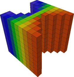
This sample vector vortex test lattice displayed
as a FaceRender with some sections transparent.
The FaceRender module properties are described below.
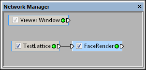
Select the FaceRender module in
the Network Manager
to display its properties in the Property
Manager.
The FaceRender module contains the following tabs in the Property Manager:
General
Customize the FaceRender properties.
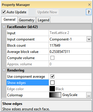
The Input property shows the source to which the module is connected. This option cannot be changed in the Property Manager, but can be changed in the Network Manager by changing the module input.
The Input component specifies which of the input components contains the data used to compute the FaceRender. To change the Input component, click the current selection and select the desired component from the list.
The Block count lists the number of cubes currently displayed by the FaceRender. This value will change as the cubes are made transparent by the Colormap or when the Geometry page is changed.
The Average block value is the average component value of all visible blocks. The average is calculated by summing the individual block values for all displayed blocks and dividing by the Block count number. This value changes as the cubes are made transparent by the Colormap or when the Geometry page is changed.
Check the box next to Compute volume to calculate the volume displayed by all colored cubes in the FaceRender module. the volume is displayed next to the Approx. volume option. Non-displayed cubes are not included in the volume calculation. Volume calculations are generated for each block. The total Approx. volume is the sum of the individual volumes for all blocks. Results are provided in cubic units based on the units of the input grid file. To make volumetric sense, the X, Y, and Z units should be the same.
To increase accuracy in the volume calculations, increase the number of cells in the X, Y, and Z directions for the lattice or Gridder.
Check the Use component average option to color every block by the average component value of the corners. If the Use component average option is unchecked, each block is colored by the component value from the lower left corner component value.
Check the box next to the Show edges command to display lines around the face for each cube. When this option is unchecked, lines are not displayed.
The Edge color displays the color of the lines that are around each cube face. To change the color, click on the existing color and select a new color from the list. Or, click the Other button to open the Colors dialog, where custom colors can be defined.
The Colormap maps component values to colors.
To change the colormap used by the FaceRender,
click the existing color bar to the right of the Colormap
command to select a different colormap from the list. Click on the desired
colormap and the FaceRender updates.
Alternatively, click the  button to open the Colormap
Editor dialog. The Colormap Editor
dialog allows you to create a custom colormap and to change the mapping
of color to data values. By default, the minimum and maximum values are
mapped to the data minimum and maximum, and a smaller range may not be
present in the cutting plane.
button to open the Colormap
Editor dialog. The Colormap Editor
dialog allows you to create a custom colormap and to change the mapping
of color to data values. By default, the minimum and maximum values are
mapped to the data minimum and maximum, and a smaller range may not be
present in the cutting plane.
Note that FaceRender cannot use partially transparent colors. Cubes are fully transparent when the Opacity value in the Colormap Editor dialog is zero. When the Opacity value in the Colormap Editor is not zero, cubes are fully opaque.
See Also