The VolRender module uses direct
volume rendering, which factors light
parameters into each point.
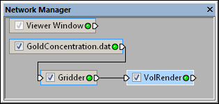
The Network | Graphics Output | VolRender command adds a VolRender module.
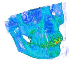
Most visualization techniques convert volume data to surfaces. The VolRender module uses an alternative technique called direct volume rendering to render voxels directly. A voxel is short for volume pixel, the smallest distinguishable box-shaped part of a three-dimensional image.
Volume rendering is a three-dimensional display of data that simulates the transmission and absorption of light through the points in the volume. Light rays are cast through the volume, where particles within the volume simultaneously emit and absorb light. The color of an individual pixel on the screen is computed by compositing the contributions from each particle intersecting the ray. This allows visualization of inhomogeneity inside objects with appropriate adjustment of the opacity.
Uniform lattice is the input type for the VolRender module.
The VolRender module creates an output geometry. It may be connected to the Graphics Output Modules. An Info Module may also be connected to the output node.
The VolRender module
uses direct
volume rendering, which factors light
parameters into each point.
The VolRender module properties are described below.
Select the VolRender module in
the Network Manager
to display its properties in the Property
Manager.
The VolRender module contains the following tabs in the Property Manager:
General

Customize the VolRender properties.
The Input property shows the source lattice to which the module is connected. This option cannot be changed in the Property Manager, but can be changed in the Network Manager by changing the module input.
The Input component specifies which of the input components contains the data used to compute the volume when there is more than one component. To change the Input component, click the current selection and select the desired component from the list.
Choose the Render method used to render the volume. Choices include 2D texture, 3D texture, and Paletted textures. The availability of the 2D textures, 3D textures, and Paletted textures is a function of your video graphics card and driver. Different cards and drivers have different features available. Some features are emulated in software and are much slower than features enabled by hardware.
For the 2D texture method, slices parallel to the object's X, Y, or Z planes— whichever is most orthogonal to the viewing direction— are rendered with a blending function to composite the pixels between slices. The color data is applied via two-dimensional texture mapping hardware on the video card. This method should work on most video hardware, but it requires three times more memory and has a "popping" effect as the graphics are rotated. This is normal and occurs when a different set of texture planes are selected to keep them as orthogonal to the viewing direction as possible. This method does not perform texture tiling, meaning that the volume dimensions after rounding up to an even power of two must be less than or equal to the value returned by the video driver.
The 3D texture method renders slices parallel to the image plane with a blending function to composite the pixels between slices. The color data is applied via three-dimensional texture mapping hardware or software emulation on the video card. This method does not exhibit the popping effect, plus it uses less memory than the 2D texture method; however, it requires three-dimensional texture support from the video hardware. This method is also more prone to aliasing effects with some data sets. This option is not shown if the current video hardware does not support it.
The Paletted textures option is available only as an extension to OpenGL. It is available with some video cards, including older NVIDIA and Intel cards. In some cases it provides faster updates (redraws) and uses one-quarter of the texture memory when the Colormap is modified. Each texel (pixel) in the texture requires only a single byte (8 bits). This is then used as an index into a table of 256 RGBA colors. There can only be 256 unique colors, but the texture maps (which can be quite large for a large three-dimensional volume) are only 1 byte per texel instead of 4 (for RGBA). For example, a 512 x 512 x 512 texture would require only 128MB rather than 512MB.
The Paletted textures option may be implemented in software on some video cards, and it is actually slower than the alternative RGBA (non-paletted) mode. This option is turned on, if available. You may wish to turn it off to compare the redraw performance.
The Paletted textures option is usually not displayed if the video card does not support it, though some video cards erroneously report that they do support the option when in fact it is not supported. The option is also not displayed when the VolRender module is attached to an image or RGBA lattice, since colors are taken directly from the RGB values in the lattice.
The 3D textures and Paletted textures may be slow if these features are emulated by software on your graphics card. Newer graphics cards enable the features through hardware and are much faster.
When the Render method is set
to 3D textures, the Number
of slices option becomes available. This is the number of 2D sample
slices that are created through the 3D volume. Increasing the number smooths
the 3D texture, but uses more memory. Decreasing the value speeds redraw,
but results in a less accurate depiction of the volume. Values range between
1 and 512. The default is 200. To change the number, highlight the existing
value and type the desired value or click and drag the  to increase or decrease the value.
The Composition options control how voxels are composited along the viewing rays. Available options are Maximum intensity, Sum intensity, and Alpha blending. To change the composition, click on the existing option and select the desired option from the list.
Maximum intensity uses the brightest pixel along each viewing ray, resulting in a display similar to an X-ray image. Note that there is no shading effect in this method. Sum intensity adds the values of the pixels along each ray. Alpha blending combines the pixels using a blending function.
The Interpolation is the method used within the lattice to interpolate values between nodes. Available options are Nearest neighbor and Trilinear. To change the interpolation, click on the existing option and select the desired option from the list.
Nearest neighbor uses the lattice node closest to the location for the value. Trilinear interpolates several lattice node values around the location to create the value. As a result, Trilinear produces a smoother gradation.
The Colormap property maps
the component value to a color. To change the colormap, click the bar
next to Colormap to display the
default color combinations. Click the desired colormap from the list.
Or, click the  button to launch
the Colormap Editor dialog. The Colormap option is not displayed
when the VolRender module is
attached to an image or RGBA lattice since colors are taken directly from
the RGB values in the lattice. Blanked lattice nodes less than the Colormap minimum are displayed
with the color specified for the Colormap
maximum. Lattice nodes that are greater than the Colormap
maximum are displayed with the color specified for the Colormap
maximum.
button to launch
the Colormap Editor dialog. The Colormap option is not displayed
when the VolRender module is
attached to an image or RGBA lattice since colors are taken directly from
the RGB values in the lattice. Blanked lattice nodes less than the Colormap minimum are displayed
with the color specified for the Colormap
maximum. Lattice nodes that are greater than the Colormap
maximum are displayed with the color specified for the Colormap
maximum.
Choose the level of opacity.
This value ranges from 0.0 (completely transparent)
to 1.0 (completely opaque). To change the level, highlight the existing
value and type a new value or click and drag the
to the desired value. The opacity is combined with the opacity specified
in the Colormap Editor dialog.
See Also